
In general, shell elements are used on bodies with a small thickness in comparison to the overall body size, beam elements are used when the length of the body is far greater than the other dimensions and solid elements are used when neither of these apply. However, the purpose of analysis, degrees of freedom, and precision of results all influence this decision.
What are the separate element types?
SOLIDWORKS can simulate a range of different element types. These ‘simplified’ element types can be used to lower the computational cost of a study while retaining almost all the accuracy, allowing for a better overall result.
Shell elements
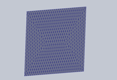
These types of elements are usually used when the body has a relatively thin cross section in relation to its overall size. They are a very commonly used type of element, almost all sheet metal parts will be simulated using this type of element. Shell elements are 2D in nature and are made up of triangular elements.
Beam elements
Beam elements are the simplest element type of the three described in this article and are the least computationally intensive.
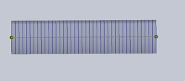
These element types are used when the body is very long in relation to its cross-sectional size. They are made up of a single line of elements and operate under the assumption that the beam has a constant cross section.
Solid elements
Solid body elements are 3D in nature and are almost always made up of tetrahedral elements.
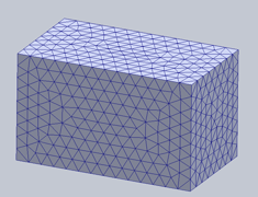
These types of elements are generally used when no single dimension on the body, be it height, width or length, is in order of magnitude greater than the others. Solid body elements are the most computationally intensive but the most robust form of mesh element, provided you can mesh enough elements (2 elements) across any feature or body.
Degrees of freedom of each element type

It’s important to understand what information each element type uses so that you can make your own decisions on the compatibility of different mesh types and in general mesh type selections.

There are 6 general degrees of freedom, 3 translational and 3 rotational. Each associated with an axis. Solid element nodes have only 3 translational degrees of freedom, and no rotational degrees of freedom.
Shell elements consist of nodes with all 6 degrees of freedom, all three translational and all three rotational elements
Beam elements consist of a node at each end of the element, with a varying number of mesh sections spaced in between the nodes. These nodes are found at the joints of the beam and each have all 6 degrees of freedom, much like the nodes of a shell element.
Choosing between the different element types
Now to the crux of the matter, when to select the different element types for your analysis.
SOLIDWORKS takes a lot of the pressure off us as users when selecting element types. When you create a body in the SOLIDWORKS model environment using weldments/structural members, it will automatically treat them as beams. However, if you create a sheet metal part it will automatically treat it as a shell element. If you decide to change the type of element used by the solver, it's as easy as right clicking the part in the simulation feature tree and selecting “treat as beam/solid/shell” depending on which type of element you wish to use.
The first thing to consider when manually selecting element types is which bodies will be central for analysis. Think about how the forces being applied to the body will affect it and decide which points are most likely to fail first or pose the greatest threat to your design. Solid elements capture the most information but are the most resource-intensive. So, you could apply a mesh refinement to give the body sufficient elements to capture the required information.
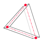
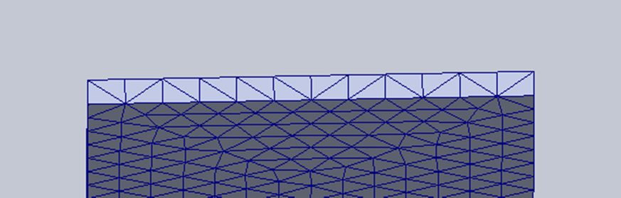
When deciding between solid or shell elements, a good rule of thumb is that you need at least two elements across any thickness for a critical area to justify the results of a solid element analysis. This element shown below would not have sufficient accuracy for an analysis, and you would need to decrease the size of the elements to properly capture the results of a solver.
However, this element would be fine enough to accurately capture the information.
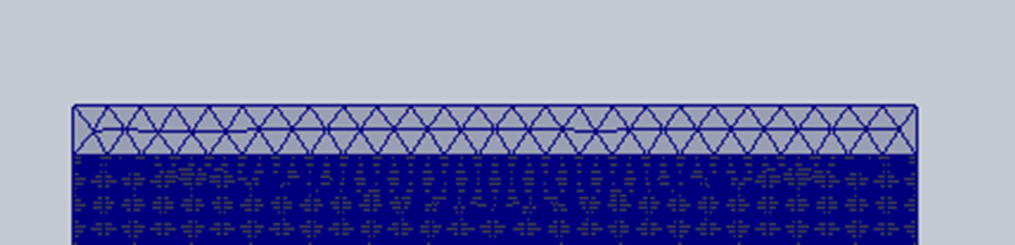
If a critical element is not able to be meshed with enough accuracy across its thickness, given the computational demand, a shell element with mesh control would be a better option. Since it would allow for a finer mesh , this results in a capture of more information without exorbitant solving times. Its important to keep in mind that 2 elements across a thickness is the bare minimum allowable precision of a mesh. Any critical section would be best captured with more than two elements.
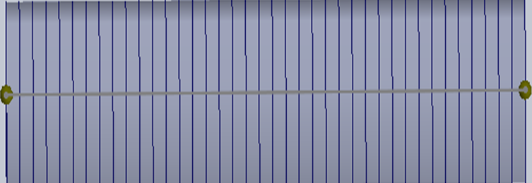
Beam elements use the greatest numerical simplification, since they consist of only two nodes, one at each joint. Therefore, beams are used if the body in question is not a critical one, or if the element is in order of magnitude longer than it is wide.
Beam elements are best used when there is a large frame system of beams with constant cross sections. Like the assembly shown below:

When considering the use of beam elements, its important to note that any simulation software will output displacements with relative accuracy even if the mesh assigned to the body is over-simple. Therefore, large frame structures are ideal for a beam analysis because the displacements of the body are paramount in any large analysis.
The choice in which type of element to use is largely reliant on the users understanding of the system and how it will deform or fail. The beauty of simulation is that it is always an iterative process. Its best practice to err on the side of oversimplification to determine which parts of the assembly will be critical. And to iteratively increase the complexity of those parts until the accuracy of the solution is ensured.
So, when in doubt, between a beam or a solid element, use the beam element to determine how critical that part is in the overall assembly, and thereafter, if the part proves to be a point of focus in the overall study, replace it with a highly complex solid element mesh for the next design iteration. This second solution would take longer to compute, but the extra computation time is worth it because you know as the designed that the part needs to be captured with accuracy
Date: 04/04/2022