
Equations and variables are quite convenient for automating design processes, especially if other dimensions are dependent on each other. This is very useful when it comes to assemblies as it is rather tedious to open new parts and update them individually. This article will go through basic steps to show how this is done.
Step 1: Rename your Dimensions
The recommended first step would be to rename the dimension name by double clicking the feature or sketch under the part of interest in the assembly tree. Double click the dimension and select the box above said dimension (see Figure 1), and give it an easily identifiable name. Make sure that “Show feature annotations” is enabled to gain easy access to feature-specific dimensions.
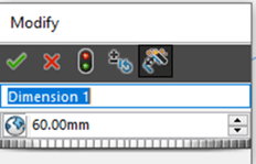
Figure 1: Modify Dimension Box
When clicking accept, it will rename the dimension thus making it easier to find. The two dimensions in this example will be the two circular surfaces renamed to “Dimension 1” and “Dimension 2 “.
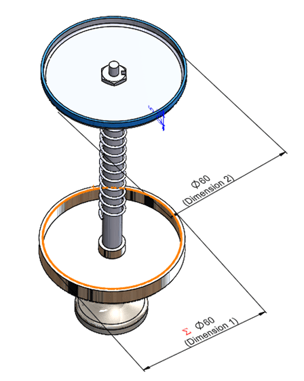
Figure 2: Example Assembly
Step 2: Declare a Global Variable
It's always good to declare your global variables ahead of time so that it is easier to get access to that variable at the moment. In this case, it will be named “Diameter”.
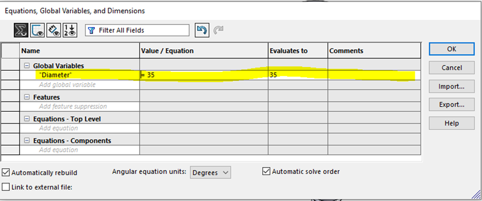
Figure 3: Equation Manager with global variable
In this example we want this “Diameter” global variable to drive “Dimension 1” and “Dimension 2” by making both equal to the global variable “Diameter”.
Note: we only make them equal in this case, you can apply any mathematical relationship that fits the design intent.
Step 3: Set Up the Equations
Either by typing out the variable name (in the format DimensionName@sketch/feature) or by selecting the actual dimensions while the correct cell is highlighted, we can add the dimensions to the “Name” Column under “Equations-Components”.
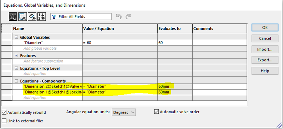
Figure 4: Equation Manager with Filled-in Equations
Step 4: Rebuild and Save
Once the document is rebuilt and saved, it will have altered the dimensions in the parts themselves and make the dimensions read-only in the separate part file to keep the assembly controlling the dimensions of the variable.
If we rebuild to any value of “Diameter”, it will be noticed that the diameters change to become equal to each other accordingly:
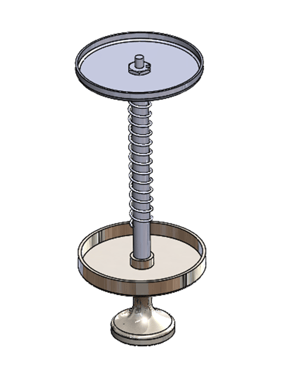
Figure 5: "Diameter” = 60mm Result
If the assembly becomes corrupt or that data is lost. it is possible to eliminate the read-only component by simply deleting the dimension and adding a new one in the part file.
Date published: 12/08/2022